

Capacitor panel Vs DG…
The application of capacitor banks is of two objectives. Reducing KVA demand from the utility and voltage improvement in the LT network.
DG users believing that capacitors are risky for DG operations.
What is often not realized is that Gensets have limited ability to meet sudden, large demands of reactive power. This results in over sizing the Genset, leading to high capital cost. Moreover, the running costs are high too, due to part-load efficiencies of Gensets being very poor. Part load operation affects engine life as well. Judicious application of fast acting capacitive compensation can be beneficial to users on all counts.
This article describes the reactive power requirements imposed on Gensets by different types of loads, their effect on the engine and also contributes the sustainability and positively impacts the environment. Effective use of electrical power is not just about financial gain; it is also about contributing to a sustainable environment. APFCR systems play a vital role in reducing energy wastage and promoting sustainable energy consumption, thereby reducing the carbon footprint and aligning with environmental sustainability goals, making a positive impact on the planet.
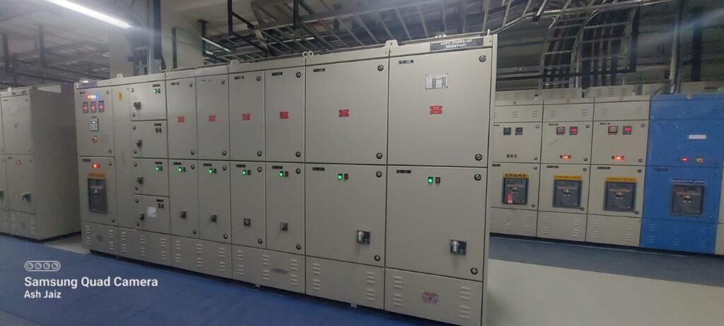
1. INTRODUCTION:
- The role of power capacitors in improving the power factor and reducing total cost of electricity in an industrial installation is well established with regard to supply of power from the electricity boards/utilities.
- When the power factor is low, more current is required to deliver the same amount of power, potentially leading to overloading and heating of conductors.
- Maintaining close to unity power factor means less reactive power flowing through the system, reducing stress on electrical equipment. This reduction of stress translates to improved performance and a longer lifespan for the equipment. Electrical equipment and appliances operate more efficiently when the power factor is close to unity, leading to reduced maintenance costs and less frequent replacements, adding to overall cost-effectiveness.
- It is thus logical to extend the above application of power capacitors when power is drawn from captive diesel gensets to optimize their performance
- It is, however, a common practice that DG set users generally will not connect capacitors on DG bus.
- The basis for such an opinion is the apprehension that the DG set may get over loaded due to the fact that the current delivered by the DG set is generally considered as the indicator of output by most DG set users. It is well known that use of capacitors will reduce the current drawn from the DG set and could thus tempt the user to add more loads on a given DG set. The other reason for such an opinion is related to the risks arising due to sustained leading power factor conditions that would occur with the use of fixed capacitors in variable load situations. The ill effects of leading power factor on the behavior of the DG sets are well recognized.
- Technological developments in the recent years, resulted in development of suitable capacitor based REACTIVE POWER COMPENSATION (RPC) Systems which are capable of being used along with DG sets in a reliable and safe manner.
- It is also observed that judicious application of this modern technology can improve the overall efficiency of DG set operation and result in considerable economic benefits to the DG set user.
2. RELEVANCE OF 0.8 POWER FACTOR
It is widely believed that the average power factor at which a DG Set should operate is 0.8. The facts stated below are specifically to correct this is technically erroneous conclusion.
- Alternators are rated in Volt-Amperes (kVA). This is logical in the sense that it specifies the maximum current the alternator can deliver at the system voltage.
- To specify the appropriate power rating of a diesel engine for a particular Alternator we have to first convert kVA to kW and thereafter kW to BHP. This can only be done if we assume a certain average Power Factor (PF) under which the DG set would operate.
- The power factor so assumed should be in line with the average power factor prevalent in the industry. A typical industrial load comprises of induction motors (typical PF of 0.8 to 0.85), non-linear loads (typical PF of 0.5 to 0.6) and combination of unity PF loads (Resistive heating and incandescent lighting). Hence assuming an average power factor of 0.8 for typical industrial loads is considered acceptable by convention.
- Consequently, a power factor of 0.8 is used for calculating the kW, which is then converted to the BHP rating of the prime mover. Knowing the BHP, it is now possible to calculate the power rating of the engine.
- It is, however, important to ensure that under actual operating conditions the Kw loading and current loading should not be exceeded
- Power Factor of loads supplied by DG sets can therefore be improved closer to unity by use of suitable Reactive Power Compensation Systems keeping in view the conditions stated above.
3. Parameters Influencing Economics of DG Set Operation:
The two major factors that influence the economics of DG set operation are:
- Mechanical Factors
- Electrical Factors
The mechanical factors: Related to the various engine aspects such as, proper lubrication, cooling, air intake systems, maintenance etc., since these issues are considered common to all situations, and they are not dealt with in this paper. It however is to be understood that for proper performance of the engine these factors are paramount and should be addressed with great care on a continuous basis.
The electrical factors: This can be broadly classified into the following:
- Alternator Efficiency
- Power losses occurring in the electrical distribution network.
- Average kW loading on the DG Set.
3.1. Alternator Efficiency:
The efficiency of an alternator is a function of the total losses that occur within the alternator. For practical purpose we can consider these as iron and copper losses, since other losses such as windage and friction losses etc. are negligible. The iron losses are generally considered to be constant irrespective of loading of the machine. However, the copper losses in the alternator are proportional to the square of the current delivered by it. Hence any reduction in current supplied by the alternator shall result in reduced losses. These losses shall be equivalent to a given amount of energy, which is a function of the time for which the alternator operates. Since this energy is supplied by the prime mover, loss reduction ultimately leads to lesser fuel consumption. The simplest technology for reducing current in a given load is to ensure that it operates at the highest feasible power factor.
The following example gives an approximate calculation to show the impact of improvement of alternator efficiency:
Consider a 3 Phase, 415V, 50Hz, 1500 kVA DG set used in an Industry for 600 hours/year with an average load of approximately 1250 kW at 0.8 PF. What is the fuel saving if PF is improved to 0.95?
The full load copper loss of the alternator is 60 kW and average yield of the DG set is 3 kWh / liter of fuel (HSD).
Rated Current of Alternator = 2000 A Current at 0.65 PF = 1500 A
Copper loss at this current = 45 kW Current at 0.93 PF = 1125 A
Copper loss at this current = 33.5 kW Saving in copper losses = 11.5 kW
For 600 hour operation = 11.5 x 600 kWh= 6900 kWh
DG set yield = 3 kWh / liter of HSD,
Potential Saving in HSD fuel = 6900/3 liters per year = 2300 liters per/year
Potential Savings in Rs. @ Rs. 100/ liter = Rs. 2.3 lakhs per year.
3.2. Power Losses occurring in the Electrical distribution network:
The total losses occurring in the electrical distribution network, is a function of the current flowing through the network and the resistance offered by the current carrying conductors/switchgear used.
Consequently, reduction of current can be realized by installing RPC Systems in the network as close to the load as feasible. This will have the added benefit of reducing losses between the alternator and the point of connection of the RPC Systems thereby resulting in further fuel savings.
While the exact savings will be case specific to each network, it will be reasonably accurate to say that savings similar to those mentioned in 3.1 can be achieved by the use of a well-engineered scheme.
3.3. Average kW loading on the DG Set:
This is the most significant factor in terms of the fuel consumed by a DG set. One can get a graph from the DG Set manufacturer that gives a typical curve of kWh/liter yield of DG sets versus the percentage loading of the set. It can be seen from the graph that most optimum performance is achieved as the loading tends towards 80% of the capability of the machine. Consequently, it should be the endeavor of all the DG set users, particularly those who are using the set as the prime source of power supply, to achieve optimum loading.
In order to understand typical loading pattern of DG sets, it is necessary to go into the process of how a DG set rating is selected. The selection process of a DG set involves the following steps:
STEP 1: Listing of all loads in terms of their operating kW and Power Factor.
STEP 2: Aggregate loading based on the step 1 multiplied by a suitable demand factor. (Since all loads may not operate simultaneously).
STEP 3: Providing additional kW capacity to meet short term peak load requirements which arise due to various load characteristics such as starting of induction motors, operation of traction loads such as lifts, cranes etc., intermittent operation of welding machines etc.,
STEP 4: Providing yet more additional kW capacity in the form of a derating factor, due to the fact that some loads are harmonic generating loads. Typical examples are DC motors, variable speed drives and other devices, which have thyristor based operation.
STEP 5: Provision of additional kW capacity to meet future needs.
Consequently, the resultant rating of the DG set arrived at by this process is generally higher than needed for regular operation. It is, therefore, quite common to find that most DG sets are loaded only between 40 to 60% of their capacity for a majority of the operating period.
As a result the practical kWh /litre of HSD achieved is lower than the actual capability of the machine. It is therefore obvious that if the loading can be increased significant savings in fuel economy can be achieved.
For example:
If total units generated = 720000 kWh/year
HSD Consumption @ 60% loading = 720000 /3.0= 240000 liters
HSD Consumption @ 80% loading = 720000 /3.6= 200000 liters
Annual Savings in HSD = 40000 litres
Annual Savings in Rs. = 40000 x Rs.100 per litre= Rs. 40 Lakhs.
The reduction of resources, as mentioned above, also contributes to sustainability and positively impacts the environment.
Benefits:
- Better Utilization of Prime Movers: The KW rating of prime movers is better utilized.
- Optimization of Ratings: The KVA rating of alternators and transformers Can be optimized as maximum.
- Reduced Transmission Line Losses: Transmission line losses are reduced.
- Decreased Voltage Drop: Voltage drop in transmission lines decreases, resulting in better regulation.
- Lower I^2R Losses: The I^2R losses are reduced, hence the heat generated in cables and bus bars is reduced. This further translates reduction of consumption of KWH / KVAH in overall.
- Locating the APFCR panels at load end instead of source side also contributing the benefits of I^2R loss significantly by not allowing the reactive power spreading the entire network. This method shall eliminate within the location of reactive power generation.
CONCLUSION
The integration of capacitor panels with diesel generator (DG) sets offers substantial advantages in terms of operational efficiency and cost savings. By effectively managing reactive power through capacitive compensation, DG sets can avoid the pitfalls of oversizing and poor part-load efficiencies. This practice not only reduces the capital and running costs but also extends the lifespan of the DG sets by optimizing their performance.
Contrary to the common belief that capacitors are unnecessary for DG sets, the article demonstrates the significant benefits of employing Reactive Power Compensation (RPC) Systems. These modern technologies enable DG sets to handle varying load conditions reliably and safely, improving the overall power factor and reducing the strain on electrical equipment.
The economic implications are clear: improved alternator efficiency and reduced power losses in the electrical distribution network lead to considerable fuel savings. Furthermore, the optimal loading of DG sets enhances their kWh/Liter yield, achieving better fuel economy and contributing to a more sustainable operation.
In conclusion, the judicious application of capacitor panels in conjunction with DG sets not only enhances their operational efficiency and reduces costs but also promotes sustainability by minimizing energy wastage and reducing the carbon footprint. This integrated approach ensures better utilization of resources, aligns with environmental sustainability goals, and offers significant economic benefits to the users.
